Creating Edge Devices
To use the Edge as a gateway to collect data and perform other functions, you need to create the Edge device and configure the appropriate communication parameters in EnOS Edge > Edge Management.
Before You Start
Ensure that you have the access to Edge management. If you do not have the access, contact your OU administrator. For more information, see Policies, Roles, and Permissions.
Create the Edge model, product, and devices. For more information, see Device Management. Note that the name of the Edge model must be EnOS_Edge_Standard_Model and the name of the Edge product must be EnOS_Edge_Standard_Product.
In EnOS Edge > Template, create a template for connection and finish its configuration. For more information, see Creating Device Templates.
Creating an Edge Device
Log in to the EnOS Console Management and select EnOS Edge > Edge Management from the left navigation menu.
Click New Edge. In the pop-up window, select the Edge devices to be added from the list, and click Confirm when you are done.
Configuring the Edge
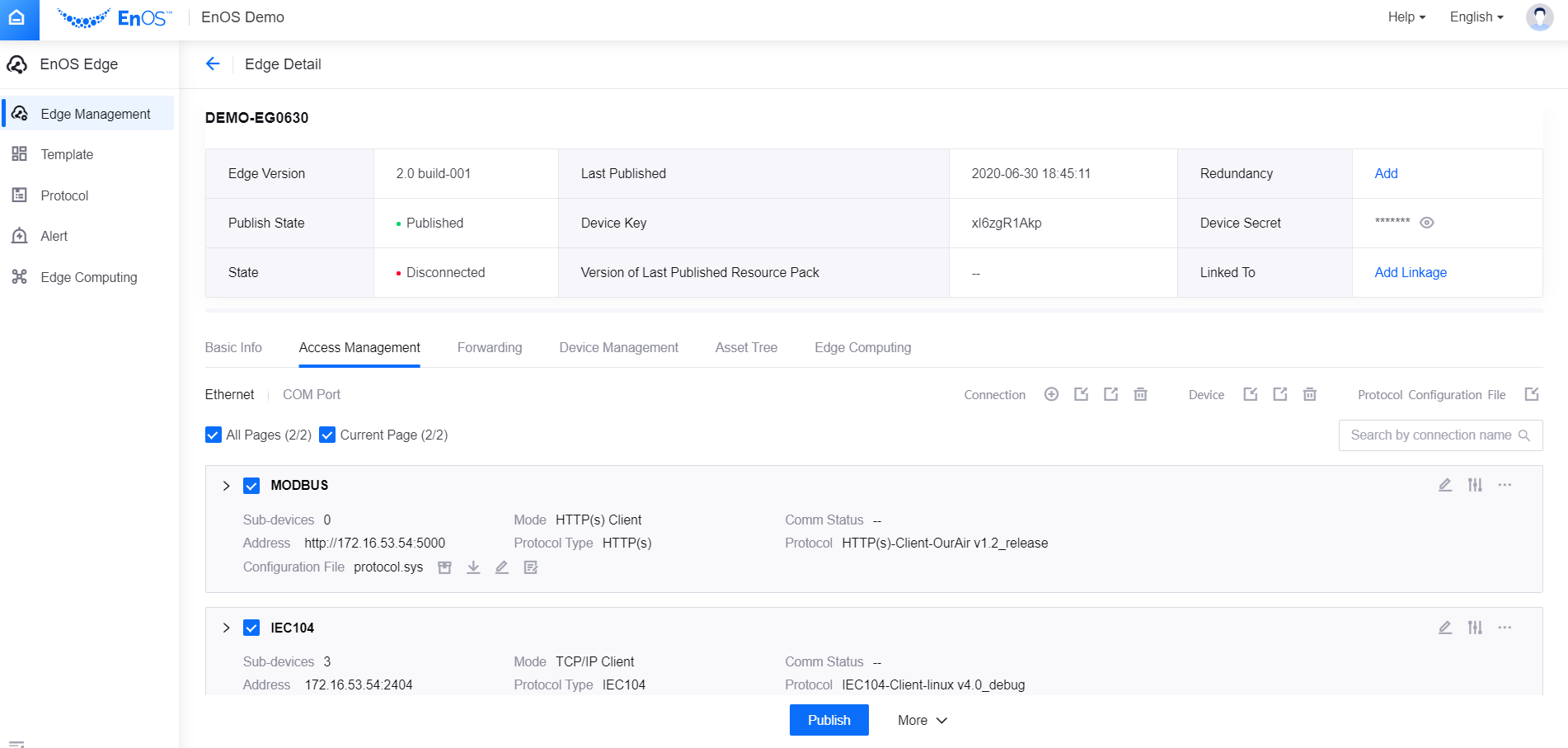
In Edge Management, click the View icon  of the newly created Edge to enter the Edge Detail page. Click More at the bottom of the page and select Download Edge Info(Main) to download the configuration file box.conf. Hand the file to the Edge deployment personnel to have the file configured, so that the added Edge instance can communicate with EnOS.
Creating a Connection
After creating an Edge device, the next step is to add a connection so that sub-devices can connect to the Edge.
In the Edge Detail page, click the Access Management tab, and select the type of the connection to be added: Ethernet or COM Port.
Click the Add Connection icon
 .
.
Adding an Ethernet Connection
In the pop-up window, fill in the following fields.
Field |
Description |
|---|---|
Name |
The identifier for the connection. |
Mode |
Whether Edge acts as a server or a client in a given protocol. Supports TCP/IP client, TCP/IP server, HTTP(s) client, HTTP(s) server, UDP, and others. |
Short Connection |
Used to determine whether the connection is a long or short connection. |
Primary Interface |
See the explanation below the table. |
Standby Interface |
See the explanation below the table. |
Protocol Type |
Select the Protocol Type in order to select a specific protocol version. |
Protocol |
Select a protocol version in the drop-down list. |
Configuration File |
After selecting the specific protocol, you can download the protocol.sys file and modify it as needed. After modifying, upload it and click Confirm to add the connection. |
The details of the Primary Interface to fill in for the different modes are as per the below.
TCP/IP Client: Fill in with the IP address and port number of the server that Edge connects to.
TCP/IP Server: Fill in with the IP address and port number of the client that is allowed to be connected to the Edge.
HTTP(s) Client: Fill in with the primary address of the HTTP(s) server that Edge connects to.
HTTP(s) Server: Fill in with the address and port number of the Edge device using the format “172.0.0.0: Port Number”.
UDP: There are two parameters in the UDP mode, “Remote Address (Primary)” and “Local Address (Primary)”. Fill in with these addresses and port numbers respectively with the primary addresses of the server and client.
Others: Select this mode when the connection does not fall into any of the above-mentioned modes. Consult support personnel on how to fill in the Primary Interface field.
The details of Standby Interface to fill in for the different modes are as per the below.
TCP/IP Client: Fill in with the IP address and port number of the standby server address that Edge connects.
TCP/IP Server: Fill in with the IP address and port number of the standby client address that is allowed to be connected to Edge.
HTTP(s) Client: Standby address is not supported in this mode. Leave it blank.
HTTP(s) Server: Standby address is not supported in this mode. Leave it blank.
UDP: There are two parameters in the UDP mode, “Remote Address (Standby)” and “Local Address (Standby)”. Fill in the remote and local addresses and port numbers respectively with the standby addresses of the server and client.
Others: Standby address is not supported in this mode. Leave it blank.
Adding a COM Port Connection
In the pop-up window, fill in the following fields.
Field |
Description |
|---|---|
Name |
The identifier for the COM port. |
Serial Port |
The type of the COM port. |
Baud Rate |
The number of bits the port is able to transfer in a second. |
Data Bit |
The length of the bits that represents data. Fixed at 8. |
Check Bit |
The bit used for error detection. |
Stop Bit |
The end of the binary data. |
Protocol Type |
Select the Protocol Type in order to select a specific protocol version. |
Protocol |
Select a protocol version in the drop-down list |
Configuration File |
After selecting the specific protocol, you can download the protocol.sys file and modify it as needed. After modifying, upload it and click OK to add the connection. |
Creating Multiple Connections at One Go
You can create or edit multiple connections at one go by first exporting and then importing the edited templates.
Note
An Edge can have a maximum of 500 connections, including those for access and forwarding.
You cannot delete any connection by removing its information from the template file.
You can obtain the protocol ID at EnOS Edge > Protocol .
Uploading Protocol Configuration for Multiple Connections in One Go
Select the connections for which you want to upload the protocol configuration.
Click the Import Configuration File icon
 beside the Protocol Configuration File. Select the edited protocol.sys to upload.
Note
Ensure that the protocol configuration works for all your selected connections.
Creating Sub-devices
After creating the connection, you will be able to add the sub-devices that use the connection.
Click the connection you created to expand it.
Click Add Device.
Select a product that the sub-device belongs to and select the sub-devices that you wish to add under this product.
In Template Setting, select the tempate for the sub-device, and click Save to add the sub-device.
Note
You must have created a template for the sub-device before this step. For more information, see Creating Device Templates.
You can add a maximum of 500 sub-devices at one go.
Editing Sub-devices
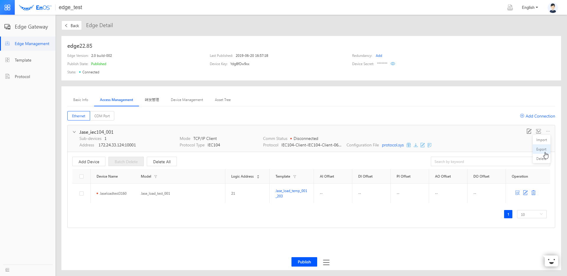
You can edit the sub-device information by clicking its Edit icon  . If you need to edit the sub-device information in batch, you can select Export at the top right of the connection and then edit the downloaded sub-device list, as shown below:
Configuring Logical Address or Offset for Sub-devices
Since multiple devices are connected using a single connection, each sub-device needs to be configured with its own logical address and offset. The configuration method is subject to the communication protocol used and its settings. Configure the logical address and offset on a device-by-device basis. You can also export the sub-device information in batch and configure it offline, then import it into the system.
Device-by-device configuration
Click on the
icon to edit the device, as shown below.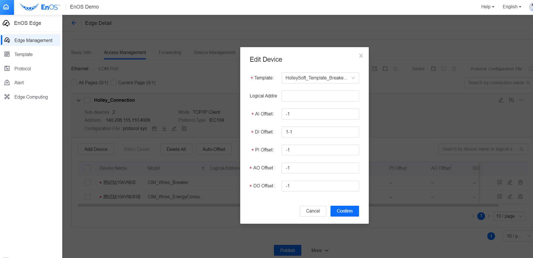
Batch configuration
Click the Export icon under More to the right of the connection to download the connection information form. After filling in required fields, click the Import icon to upload the edited information form.
Note
The exported table supports configuring AI, DI, PI, AO, DO, and PO offsets. The format is n-n, where n is an integer, such as 0-50. When there are multiple offsets at the same time, use # to separate them, such as 0-50#1000-1050.
Adding a Sub-device to Multiple Connections
You can add one sub-device to multiple connections with the steps below.
In Access Management, check multiple connections to add a device to. Click the Export Device Addition Template icon
 to download the template file.
Fill in the form with the device information to be added and upload the template file.
Publishing EnOS Edge
After you have configured the connections and their sub-devices, click Publish at the bottom of the Edge Detail page to effectuate your Edge configuration.
Testing Connections
You can use the test function to verify your configuration. For more information, see Testing Communications.