Connecting Devices to EnOS through EnOS Edge
This tutorial walks you through how to connect devices to EnOS Cloud through EnOS Edge.
EnOS Edge, as a software, can be deployed on various hardware. For this tutorial, the EnOS Edge software is installed on a Dell Edge Gateway 3000. The deployment of Edge software on a hardware does not require any user action. For Edge deployment, contact the EnOS Edge deployment personnel.
Scenario
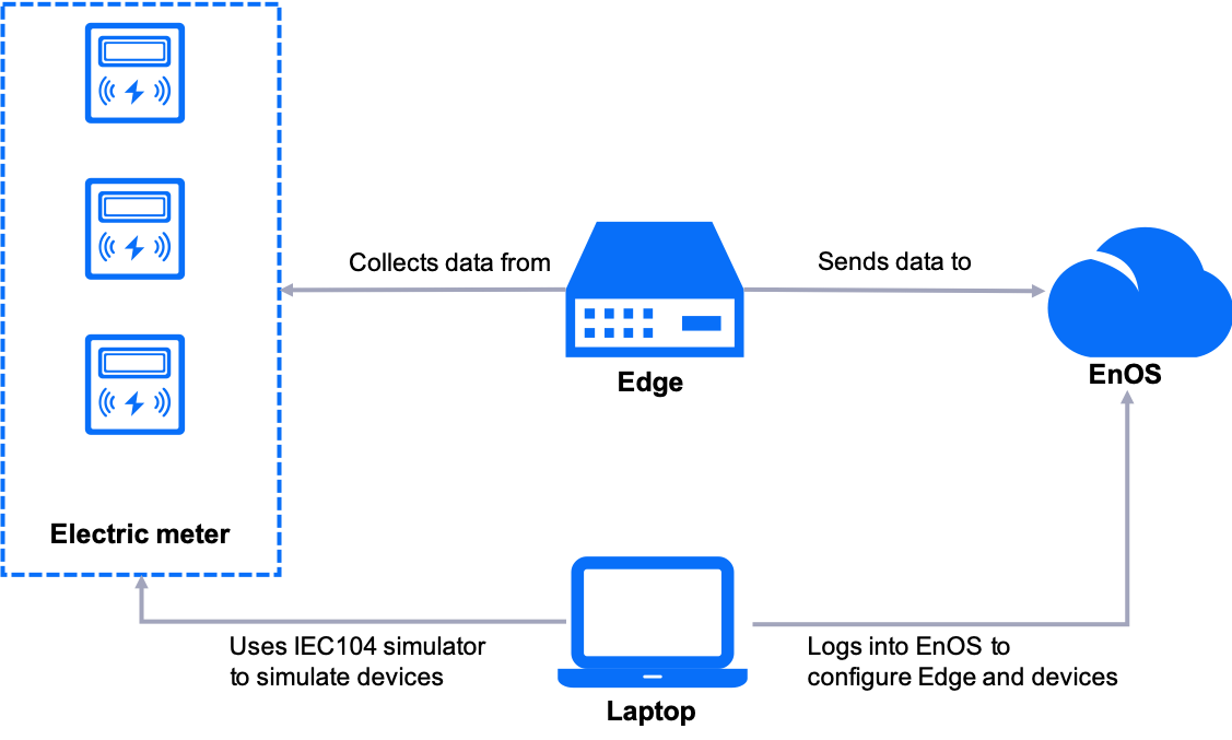
An IEC104 simulator is installed on a laptop to simulate three electric meters that communicate through the IEC104 protocol.
Note
The tools can only be installed on a separate machine (not Envision Digital office laptop or PC) under a controlled environment for testing purpose only. DO NOT connect to the office network. Uninstall it after testing.
The simulated devices are connected to the EnOS Edge as sub-devices.
EnOS Edge is connected to the network to communicate with EnOS Cloud through the standard protocol, MQTT.
Step 1: Defining Models
A model is the abstraction of the features of an object connected to EnOS. It defines the features of a device, including the attributes, measurement points, services, and events. For more information about models, see Device Modeling.
The model of the EnOS Edge is provided as a public model in EnOS. In the EnOS Management Console, click Model from the left navigation menu, click the Public tab, and search for EnOS_Edge_Standard_Model. You can view its basic information and feature definitions by clicking the View icon  .
.
In this step, we need to create models for the simulated sub-devices before they can be connected to EnOS.
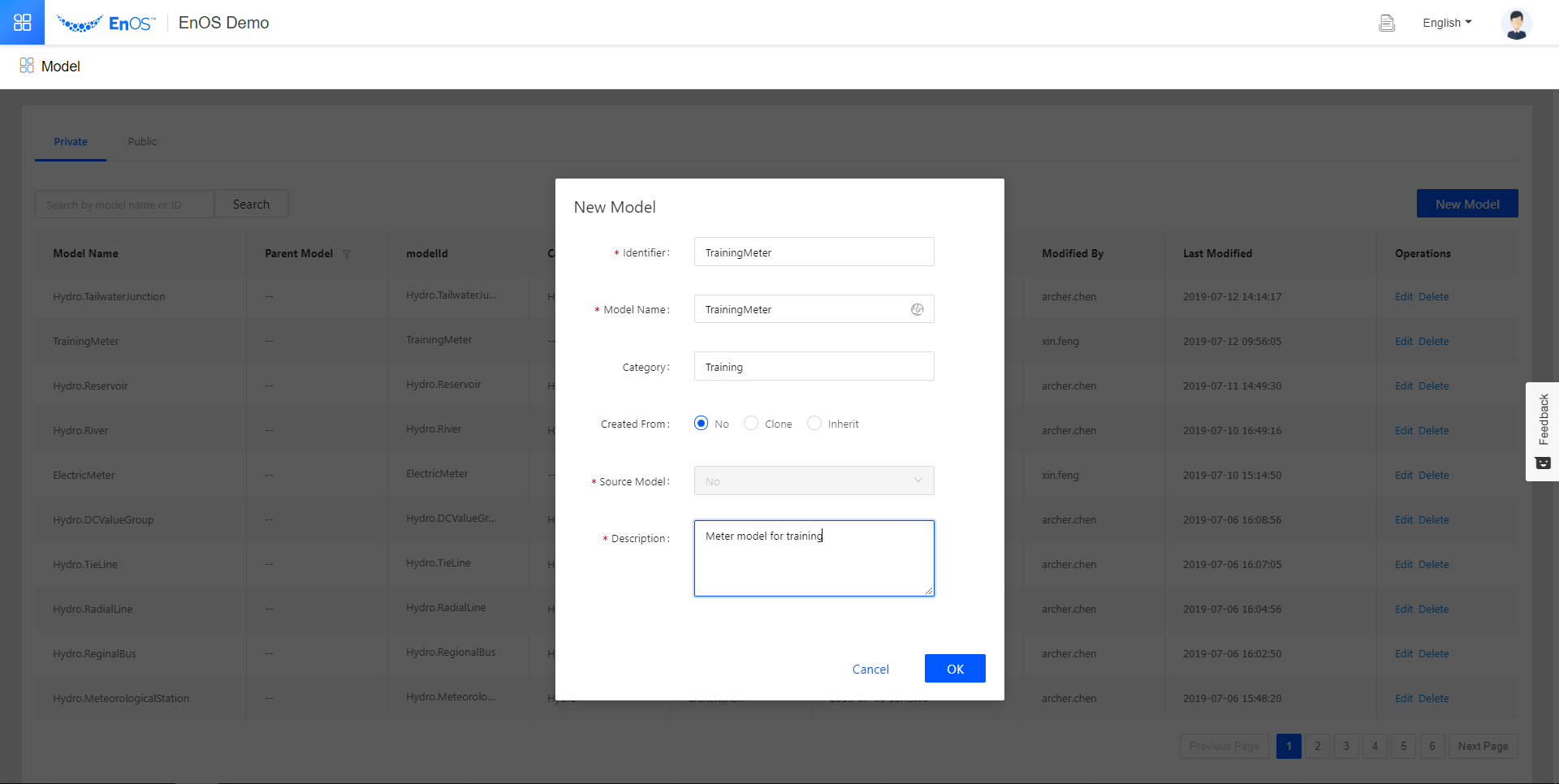
Go to Model. At the Private tab, click New Model.
In the New Model pop-up, fill in the following fields.
Model Information¶ Field
Value
Identifier
TrainingMeter
Model Name
TrainingMeter
Catetory
Training
Created From
No
Source Model
No
Description
Meter model for training
Click the Edit icon
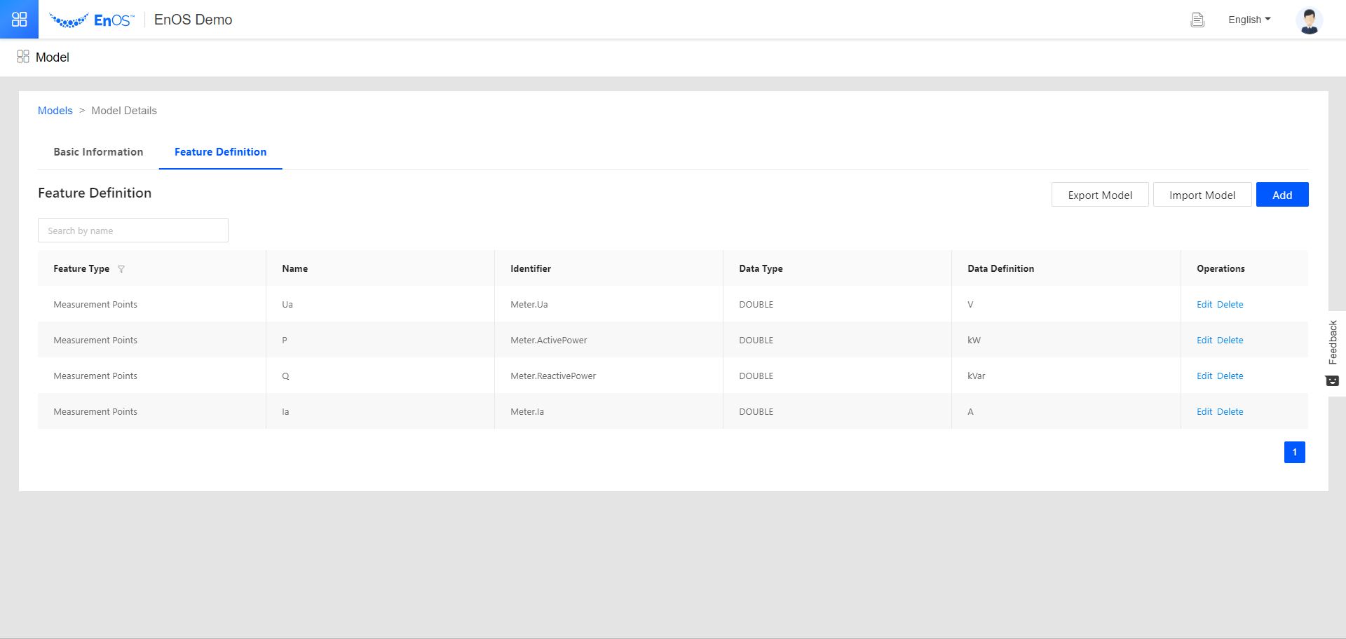
 for TrainingMeter. Go to the Feature Definition tab and create 4 measurement points by doing the following for each measurement point.
Click Add > Create Custom Feature.
Fill in the fields as per the table below in the pop-up.
Click Confirm.
Measurement Point Information¶ Measurement Point
Feature Type
Name
Identifier
Point Type
Quality Indicator
Data Type
Default Value
Unit
Required
Description
1
Measurement Points
Ua
Meter.Ua
AI
No
double
Electric Potential: volt | V
Leave it blank
2
Measurement Points
P
Meter.ActivePower
AI
No
double
Power: kilowatt | kW
Leave it blank
3
Measurement Points
Q
Meter.ReactivePower
AI
No
double
Power: KiloVolt Ampere Reactive | kVar
Leave it blank
4
Measurement Points
Ia
Meter.Ia
AI
No
double
Electric Current: ampere | A
Leave it blank
You have now created the model for the simulated sub-devices we will use to connect to the Edge.
Step 2: Creating Products
Now that we have defined the model, we need to create products based on the device and Edge models.
A product is a collection of devices with identical features. While a model abstracts device features from 4 aspects (atrributes, measurement points, services, and events), a product further defines the communication parameters for the device.
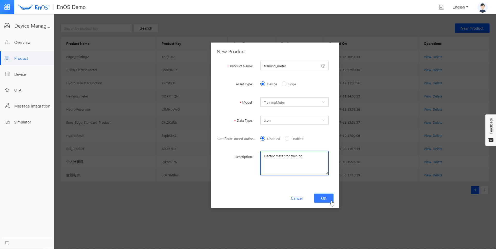
Go to Asset Management > Product. Click New Product.
In the New Product pop-up, fill in the following fields.
Product Information for Simulated Devices¶ Field
Value
Product Name
training_meter
Asset Type
Device
Model
TrainingMeter
Data Type
JSON
Certificate-Based Authentication
Disabled
Description
Electric meter for training
You have created the product for simulated meters. Now do the same thing for the Edge device.

We are now ready to create the device instances on EnOS.
Step 3: Creating Device Instances
A device is created from a product so that it inherits not only the basic features of the model, but also the communication parameters of the product (such as the product key and device key used for authentication). In this step we need to create devices on EnOS for the Edge and its sub-devices.
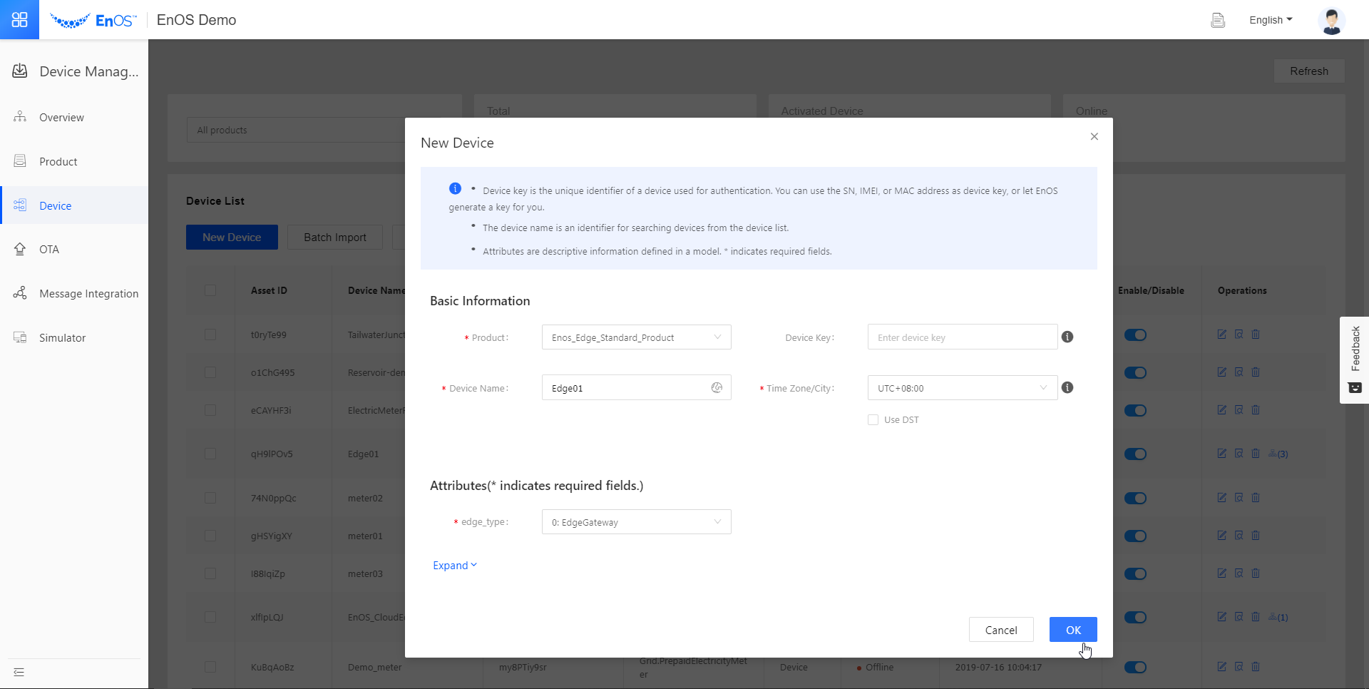
Go to Asset Management > Device Asset annd click New Device.
In the New Device pop-up window, fill in the following fields.
Device Information for Edge¶ Field
Value
Product
EnOS_Edge_Standard_Product
Device Key
Leave it blank
Device Name
Edge01
Time Zone/City
UTC+08:00
edge_type
0: EdgeGateway
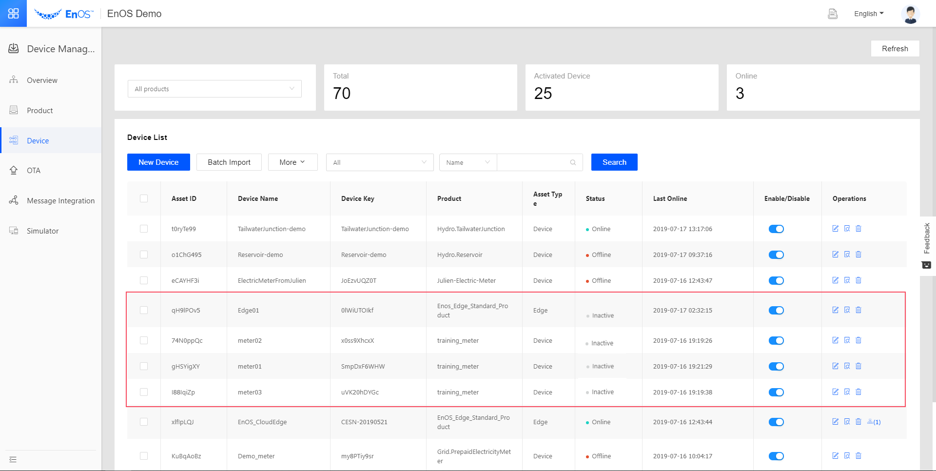
A device instance for Edge is now created. For the sub-devices, we will use our laptop to simulate three electric meters that will be connected to Edge. We will name them “meter01”, “meter02”, and “meter03”. Repeat the steps for creating a device instance and use the information as per the below for the 3 sub-devices.
Field |
Value |
|---|---|
Product |
training_meter |
Device Key |
Leave it blank |
Device Name |
meter01, meter02, and meter03 |
Time Zone/City |
UTC+08:00 |
The Edge and sub-device instances are now in the device list.
Step 4: Creating the Asset Tree and Binding the Edge
For Edge to function properly, we need to register the edge device in Asset Tree. To do that, we will first create an asset tree and bind the created Edge device to the tree as a node. You need an OU administrator account to create an asset tree.
Go to Asset Tree. Click
 in the upper left corner.
In the Create Asset Tree pop-up, enter the “Edge02” for the name and click Next.
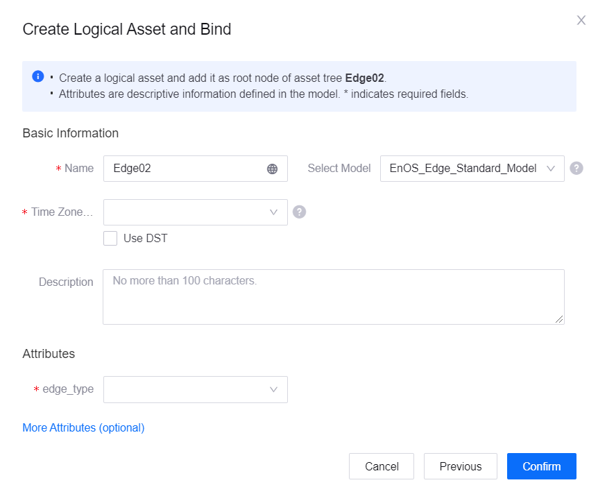
Click Create an Asset and Bind, click Next, and fill in the following fields.
Asset Tree Information for Edge¶ Field
Value
Name
Edge02
Select Model
EnOS_Edge_Standard_Model
Time Zone/City
UTC+08:00
Description
Leave it blank
edge_type
0: EdgeGateway
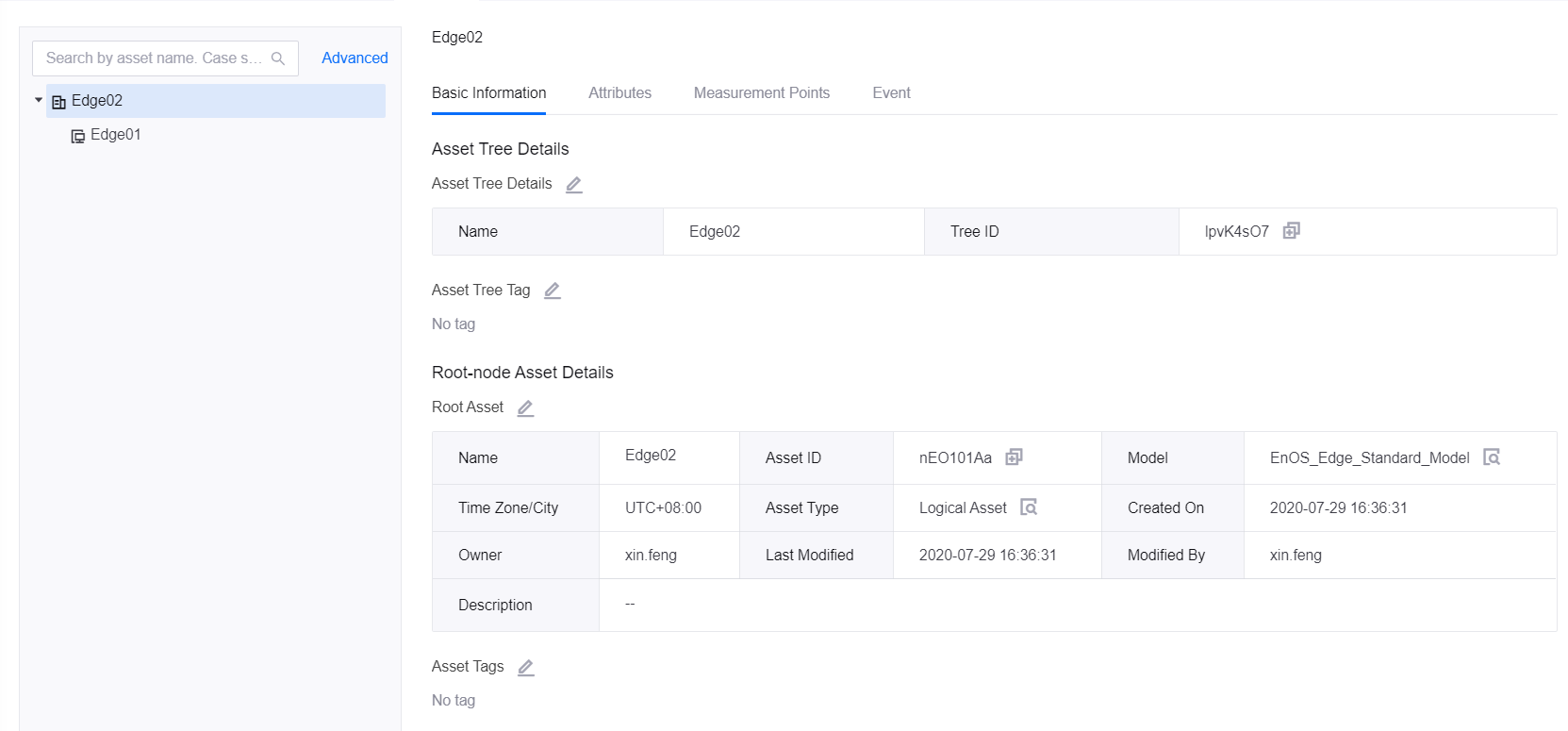
Click the + to the right of the asset tree name “Edge02” in the left panel.
In the New Sub-node pop-up, select Bind to an Existing Asset and click Next.
Enter “Edge01” for Device Name and click Query. Select the “Edge01” device in the result list and click Confirm.
The Edge device is now bound to the asset tree as a sub-node.
Step 5: Creating Device Template to Map Data Points
The device template determines how data collected from a device by using a protocol is mapped to the model measurement points defined on EnOS Cloud.
Go to EnOS Edge > Template and click New Template.
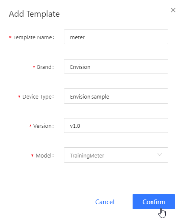
In the Add Template pop-up and fill in the following fields.
Asset Tree Information for Edge¶ Field
Value
Template Name
meter
Brand
Envision (or any brand as you see fit)
Device Type
Envision sample (or any type as you see fit)
Version
v1.0 (or any random version number)
Model
TrainingMeter
Find the template you just created and click its Edit icon
.In the Edit Template pop-up, click the Download Template icon
 . Next, click the Download icon
  to download the
 point.xlsxof the “IEC104-Client-linux v3.0_debug” as this is the protocol we are going to use for this tutorial.Open the
point.xlsxyou just downloaded.point.xlsxcontains the attributes of the collection and control points to be reported to Edge. Since we have defined 4 measurement points for the device model in Step 1, we need to create 4 collection points so that they can be mapped to the 4 measurement points later.When you first open the
point.xlsx, it will look like the following with the Chinese characters from left to right on the first row meaning measurement point, point number, value type, point type, coefficient, base value, and alias.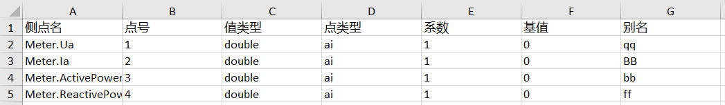
Let us edit
point.xlsxso that it looks like this.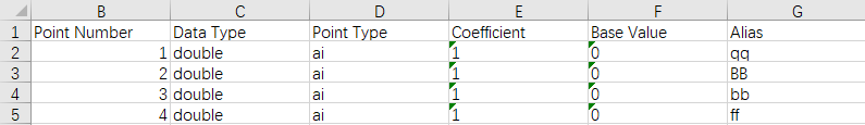
As you can see, we changed the measurement point, value type, and point type to match the “Identifier”, “Data Type”, and “Point Type” defined in the model in Step 1.
Note
For point numbers, they must be continuous positive integers and follow the order in which the collection points are sent to EnOS as prescribed in the channel table.
Save and close
point.xlsx.Go back to EnOS Edge > Template > Edit Template. Click the Upload icon
 to upload the
 point.xlsxyou just edited.In the Edit Template page, click the Mapping Points icon
 for each measurement point.
In the pop-up, select the collection point in the Collect tab with the description that matches the measurement point’s identifier and click Confirm.
By doing this, you map the measurement points defined in our model to the collection points defined in
point.xlsx.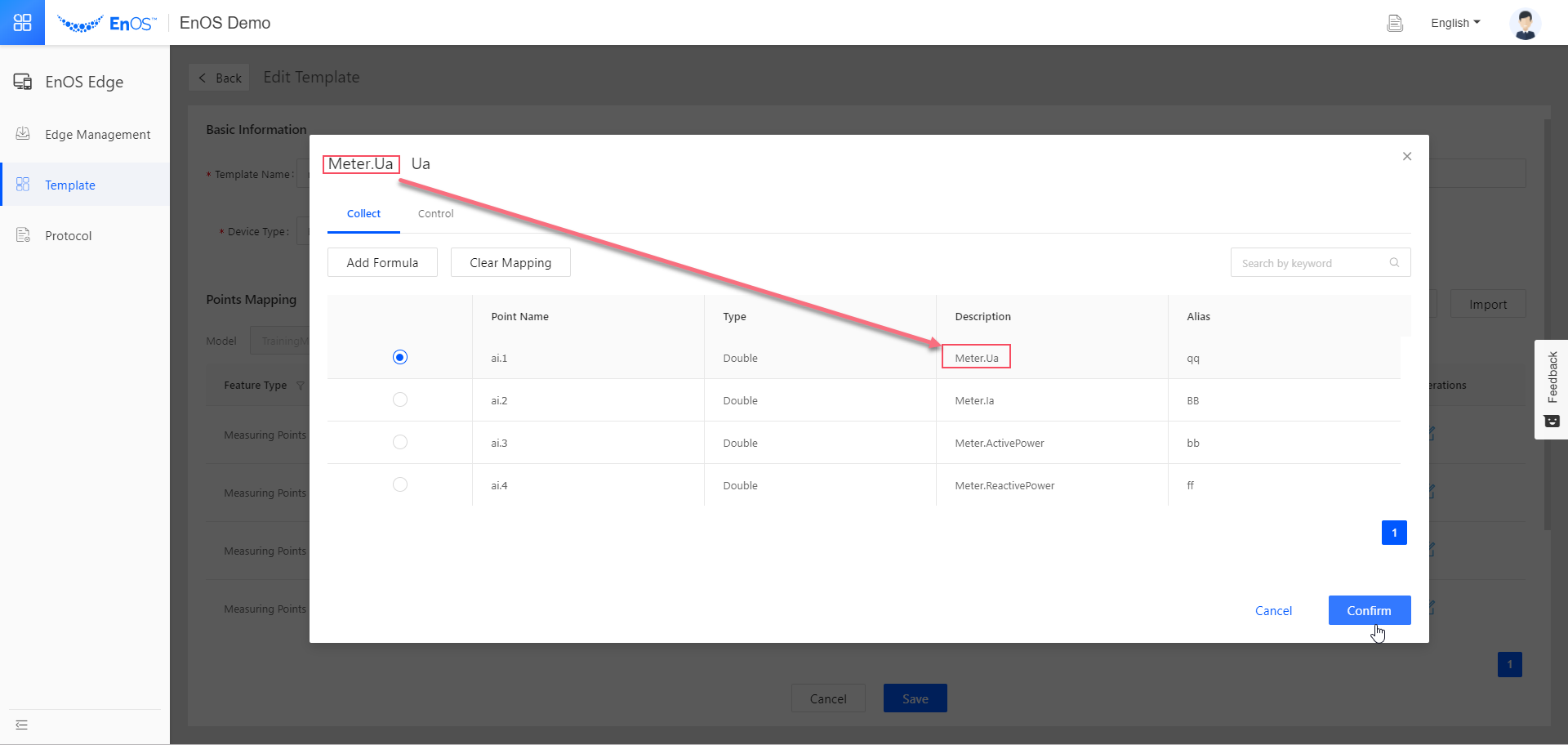
Repeat #8 and #9 until all the measurement points are properly mapped. Then click Save.
By now we have completed configuring our template. This means that when we set up our Edge and connects it to EnOS Cloud and thesub-devices, the collection points from the simulated sub-devices can be properly mapped to the measurement points defined in the model.
Step 6: Configuring Edge
In this step, we will add the Edge device we created in Asset Management to Edge Management, configure its connection with the sub-devices, and configure the offset value for the measurement points of each sub-device.
Go to EnOS Edge > Edge Management and click New Edge.
In the New Edge pop-up window, select the Edge we added and click Confirm.
Click the View icon
of the Edge you just added.In the Edge Detail page, click More beside the Publish button and select Download Edge Info(Main) to download the configuration file for the Edge device.
Give the downloaded
box.confto an EnOS Edge support personnel and let the support personnel configure the Edge device using thebox.conf. After the support personnel has configured the Edge device, it can connect to EnOS once it is powered on.In the Edge Detail page, click the Access Management tab. Click the Add Connection icon
 in the Ethernet tab.
In the Add Connection pop-up window, fill in the following fields.
Asset Tree Information for Edge¶ Field
Value
Name
Meter_Training
Mode
TCP/IP Client
Short Connection
Disabled
Dynamic Template
Disabled
Primary Interface
The IPv4 Address of your laptop. For port you can give it a random integer grater than or equals to 1000.
Standby Interface
Leave it blank
Protocol Type
IEC104
Protocol
IEC104-Client-linux v3.0_release
Configuration File
No action is required. But you might have to modify the configuration if you use other protocols or as needed.
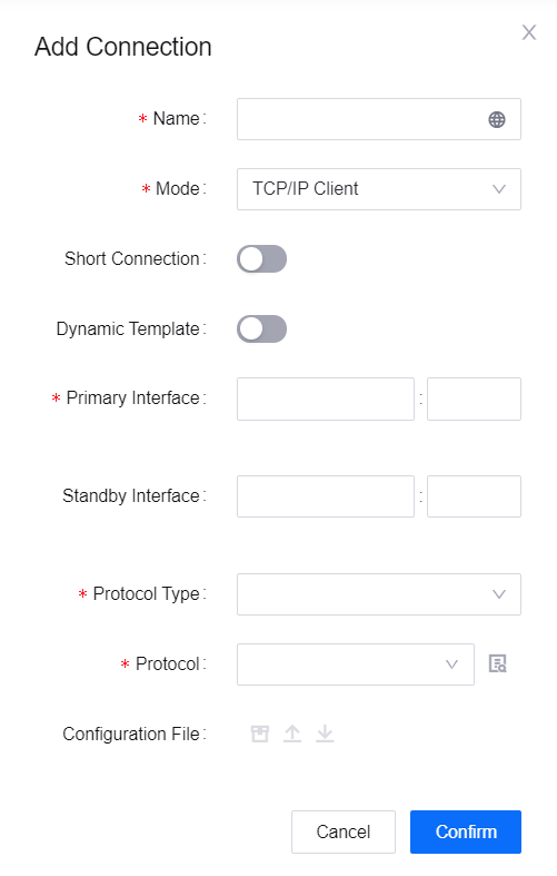
Click Confirm. You have now created a connection for the Edge device.
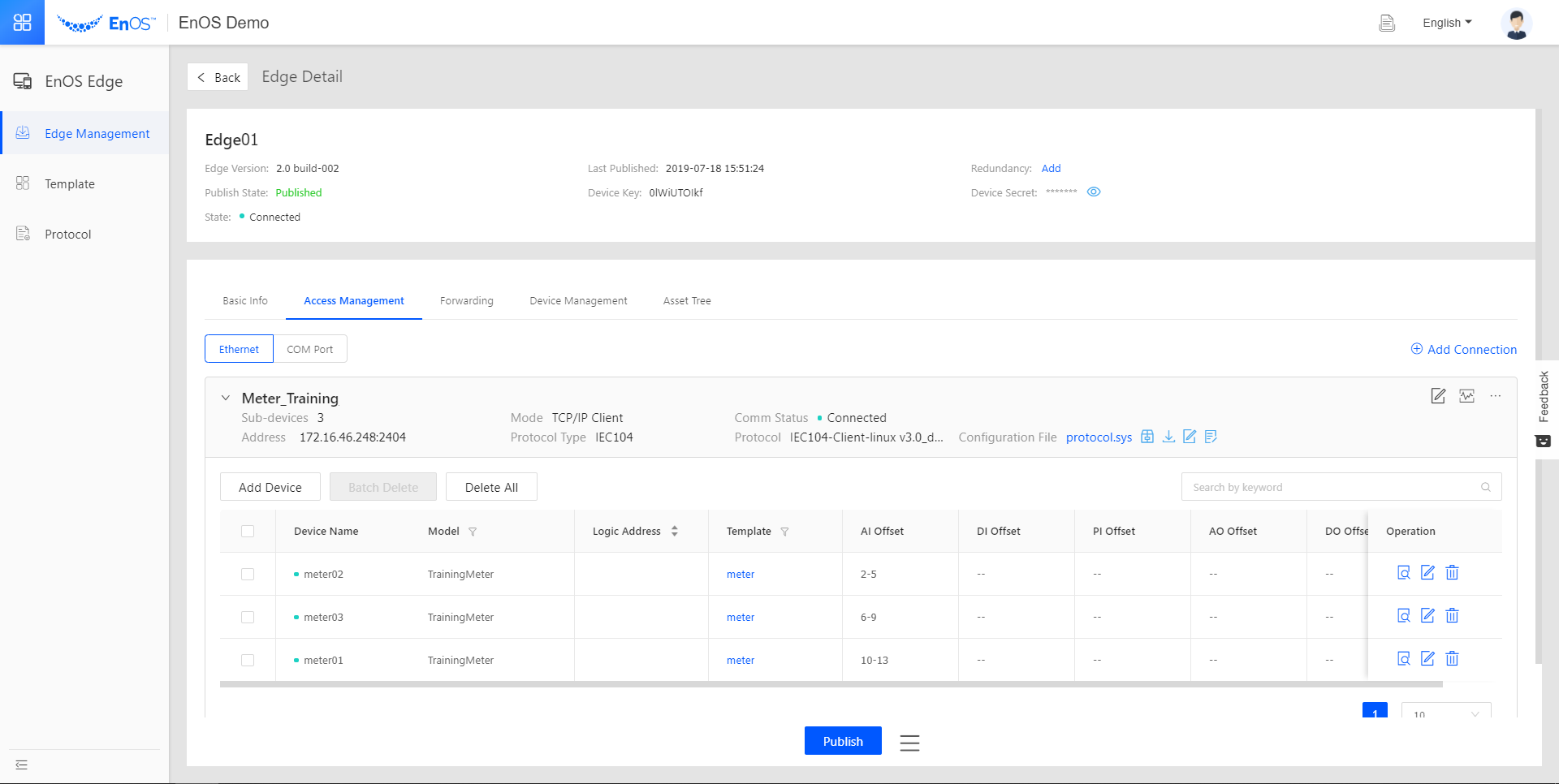
Click to expand the connection you just created.
Click Add Device. In the Add Device window, select the product training_meter we just created, and check all three devices meter01, meter02, and meter03.
Under Template Setting, select the template we created for these device, meter.
Click Save.
Click to expand the connection. In the device list, click the Edit icon
of any device.In the Edit Device pop-up, set the AI Offset using the format “a-b#c-d”, with a, b, c, d representing integers and a < b, c < d. “-” indicates that this is a value range, while “#” indicates that the range can be discontinuous.
The offset value range is used to identify which values in the simulation scheme file belong to this device.
We need to do a little bit of math here. Since there are 4 measurement points we need to map to every device, we must make sure that there are 4 integers in the value ranges of one device, both ends of a range included.
In this example, in order to have four integers for one device. We can set the AI Offset as “2-5” or “2-3#6-7”. We shall use “2-5” for convenience’s sake.
Click Confirm.
Repeat #14 and #15 for the remaining devices. Ensure that all the four AI offset ranges are unique, and do not overlap.
Step 7: Installing and Configuring the IEC104 Protocol Simulator
We are almost there! In this step, we will install a protocol simulator, which simulates devices that send measurement point data in the IEC104 protocol to Edge, on our laptop. We will then configure how this simulator sends data to EnOS and finally, kick off the simulation.
Download the
IECServer.exeandiec_ai_12.properties.Open
iec_ai_12.propertieswith a text editor (we recommend Notepad++).Each item in this file represents a measurement point. As we have 4 measurement points each for 3 electric meters, the total measurement points is 12, as there are in this file.
We need to change their “IOB” values so that they can be properly mapped to the measurement points of each device.
Dividing the items into 3 groups, ITEM1 to ITEM4, ITEM5 to ITEM8, and ITEM9 to ITEM12, each group represents the 4 measurement points of an electric meter.
Suppose ITEM1 to ITEM4 are the measurement points of meter01, whose AI offset is 2-5 as configured in Step 6. Then the IOB values of ITEM1 to ITEM4 should be 16385+2, 16385+3, 16385+4, 16385+5, i.e., 16387, 16388, 16389, 16390. 16385 is the start address for the AI data prescribed in the protocol IEC104’s
protocol.sys.Repeat this step for all items in this configuration file and save your changes.
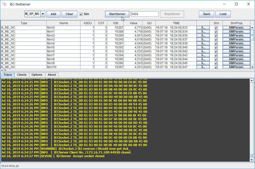
Open
IECServer.exe, click Load, locate and select the configuraion file you just edited, and click Open to load the configuraion file into the simulator.Fill in the box next to the StartServer button with the same port as you set as the address of your sub-device connection. In this case, it is 2404.
You can find the port number as follows.
Go to EnOS Edge > Edge Management.
Click the View icon
to go to the Edge Detail page of the Edge you created.Click to the Access Management tab, and you can see the port number in the Address field of the connection.
Click StartServer to start the simulation.
Step 8: Viewing the Data on EnOS Console
Now let us go to EnOS Edge > Edge Management, click the View icon for the Edge, and go to the Access Management tab. Click to expand the connection. The devices now have a green light in front of them, indicating a successful connection.
Click the View icon of any device to view the data that is coming from our simulator.
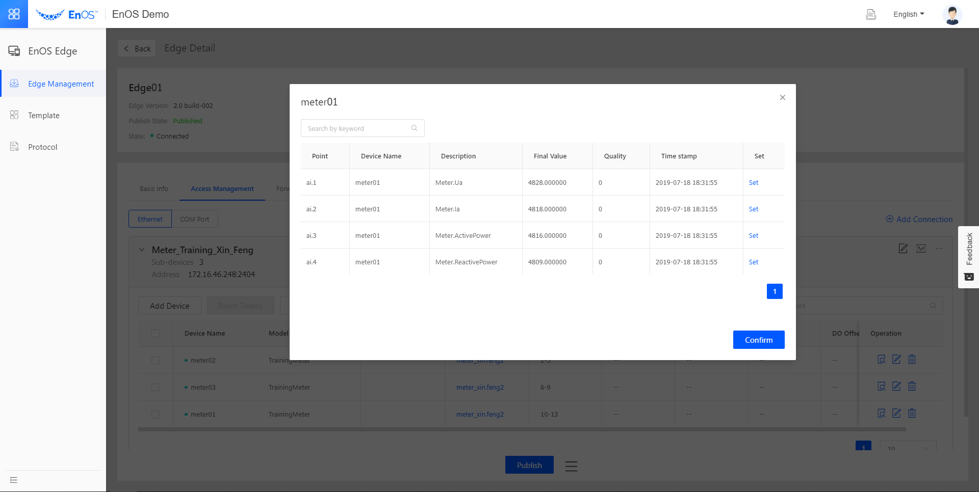
Congratulations! You have learnt how to connect an Edge device to EnOS, and use a simulator to simulate devices transferring data through Edge to EnOS cloud.