Creating Flows
An integration flow is made up of a series of nodes that processes data for the integration of devices across enterprises and organizations. Integration flows can be used for various purposes such as data forwarding, converting instruction formats for communicating between different devices, etc.
This section shows how to create an integration flow.
Prerequisites
For cloud flows, ensure that the assets for integrating the data to exist in EnOS. If not, you need to create them first. For more information about creating models/products/devices, see Managing Models and Connecting and Managing Devices in the Cloud.
Ensure that you have read the limitations for creating flows. See Limitations.
Step 1: Create New Flow
There are two ways to create an integration flow.
Create from Scratch
Log in to EnOS Application Portal > Developer Console and click Device Data Integration > Flow Designer for cloud/remote flows or Device Data Integration > Integration Agent for remote flows from the left navigation menu.
Click New Integration Flow.
Click Create from Scratch. Enter the flow name and description, and click OK.
Create from Template
There are two ways you can create a flow from an integration template.
From Device Data Integration > Flow Designer (cloud/remote flows) or Device Data Integration > Integration Agent (remote flow).
Click New Integration Flow.
Click Create from Template. Select an integration template from the drop-down, enter the flow name and description, and click OK. Existing integration templates can be viewed at Device Data Integration > Integration Templates.
From Device Data Integration > Integration Templates
In either of the three template type tabs, click the integration template to create the flow from. You can toggle between cloud and remote flow templates by selecting Cloud Flow or Remote Flow from the top right drop-down.
Click the Create Flow from Template icon at the top of the design canvas, edit the flow name and description, and click OK.
Step 2: Design the Flow
You will enter the Flow Designer page with a blank canvas if a flow is created from scratch. If created from an integration template, the canvas will show the nodes of the flow, which can be edited as per needed.
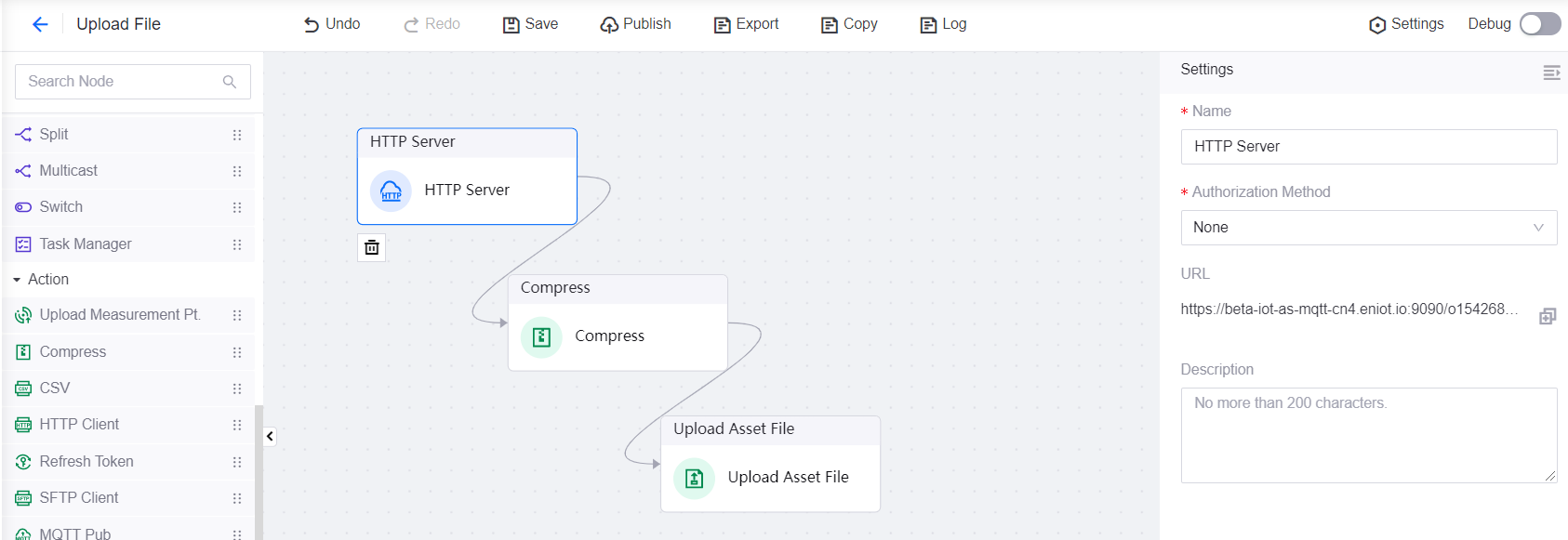
Drag and drop a node from the list of nodes on the left.
Configure the node settings on the right panel. For more information about each node’s settings, see List of Nodes.
Repeat both steps above for the other nodes for your flow. If you need to delete a node, select it and click its Delete icon
 .
.Connect all the nodes to make a flow. To connect two nodes, drag a line from a node’s exit point to another node’s entry point. To delete a connector, click on it and press “Delete” on your keyboard. Note that some nodes do not have an entry or exit point. These nodes are used as the start or end nodes of a flow.
You can click Undo or Redo during the creation process.
For cloud flows, you can toggle on the Debug switch on the top right to record the logs of the nodes in the flow. Node logs are stored for a maximum period of 7 days. For more information on logs, see Viewing Cloud Flow Logs.
Click Save to save your flow.
Results
The created flow is now in the list of flows at the Flow Designer page, which shows the list of cloud flows by default. To change to the list of remote flows, select Remote Flow from the drop-down at the top right.