Adding an EnOS Edge Gateway
The Edge gateway needs to be configured before connect the sub-device to the edge gateway. This article describes how to configure edge gateway in order to establish the connection between edge gateway and the sub device.
Before You Start
You must have obtained the serial number (SN) of the Edge gateway.
You must have completed the initialization of the Edge gateway. The initialization of the Edge gateway hardware is usually done by the Envision project team. For more information, consult the Envision project manager.
Step 1: Adding the Edge Gateway
In the EnOS Management Console, click EnOS Edge > Edge Management from the left navigation menu.
Click Add.
In the pop-up window, enter the name and serial number of the Edge gateway.
Click Save to complete creating Edge gateway.
After the Edge gateway is successfully added, in the Edge Management page, you can view the name, SN, version, the current communication status, and the publish status of each Edge, as shown in below figure:
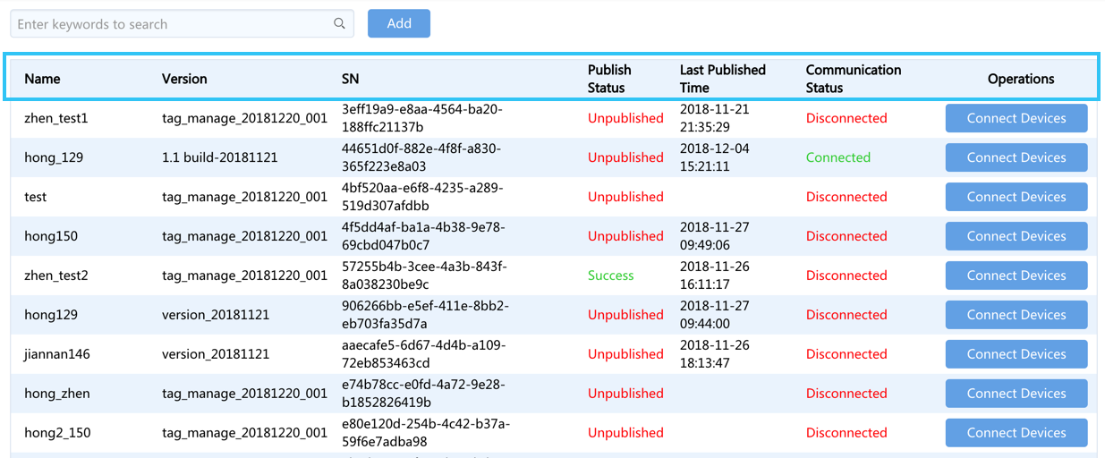
Step 2: Connecting the Sub-device to the Edge Gateway
After the Edge gateway is added, you can connect the sub-device to the edge gateway.
Click Connect Devices after the Edge gateway to be connect to open the configuration page.
In the configuration page, you must finish the following configuration in order to establish the connection between the sub-device and the edge gateway.
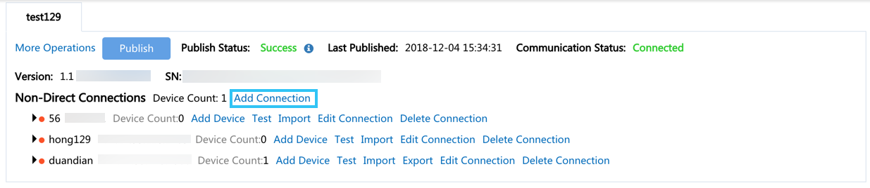
Adding Connection
Firstly, you need to configure the connection for the Edge gateway.
According to the actual needs, multiple connections can be added under one Edge gateway, and the connection method must be selected according to the type of the protocol.
Click Add Connection next to the Non-Direct Connections.
In the pop-up window, enter the name of the connection, select the connection mode, and set the connection parameters according to the selected connection method.
Note
Usually the Edge is not connect directly to the end server or device. Instead, the edge is connect to a network gateway, and then connect to the end server or device via this network gateway. Therefore, you need to know the mapping relationship between the IP address and port number of the network gateway and the edge gateway.
As shown in the following figure, Edge is used as the TCP/IP client, so the configured connection parameters are the IP address and port number of the server.
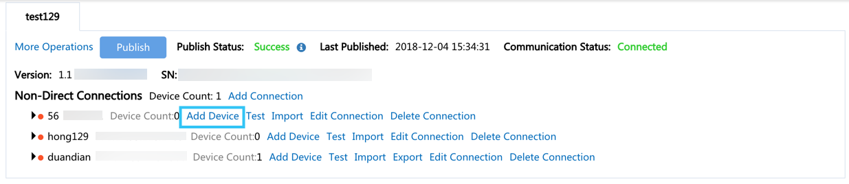
Adding Devices
After adding connection, the next step is to add device to this connection. In this step, you’ll add the device and configure the basic information.
Step 1: Add Devices
Click Add Device next to the connection.
In the pop-up window,
select the product to which you want to add the devices.
select the devices you want to add.
select the device template that the device needs to be associated with.
Note
You must first select the same kind of devices, then you can select the device template that the devices to be associated with.
The device template is used as the device communication driver, which includes the device communication point table, communication protocol, protocol configuration file and other information. For more information, see Creating and Managing Device Templates
Click Save to add the device.
Step 2: Update Basic Information
If the basic information of the added device needs to be updated, you can modify the information in the following approach:
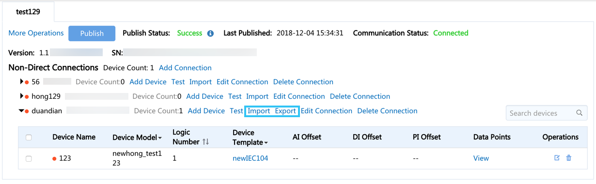
Click Export next to device connection to export the device connection information table.
Update the basic information in device connection information table .
Click Import to upload the information table.
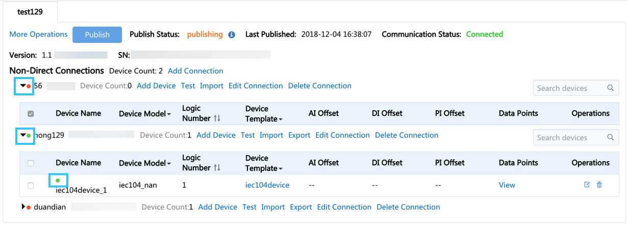
You can find the Import and Export button as shown below:
Configuring Logical Addresses or Offsets
Since multiple devices are connected under one connection, the logical address and corresponding offset must be configured for each device. The configuration of each device depends on the communication protocol used and its settings.
You can configure the device by two ways:
One by one.
In batches by updating device connection information table.
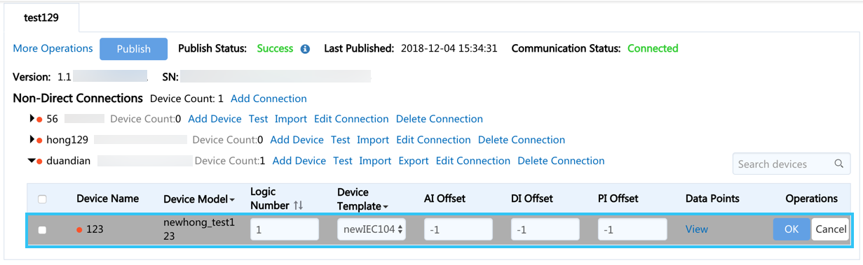
Configure the device one by one in the following approach:
Click Edit after the device to be edit.
Edit the configuration according to your requirement and then click OK.
You can configure the device in batches in the following approach:
Click Export after the device connection to download the device connection information table.
Edit the device connection information table according to your requirement.
The table supports the configuration of the AI, DI, PI, AO, DO, and PO offsets. The basic configuration method is use dash-connection, such as
0-50, when there are multiple offsets, you can use#to separate multiple values, such as0-50#1000-1050.Click Import to upload the information table.
Publishing Configuration
After completing the above configurations, you need to publish the configuration to the Edge.
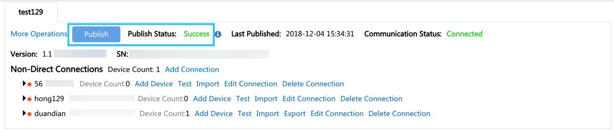
Click Publish to publish the configuration to the corresponding edge gateway and view the publish status. The configuration will not take effect until it is published.
You can find the Publish button and the publish status as shown below:
Step 3: Testing Communication
After completing and publishing the configuration to the edge gateway, you need to check whether the configuration is correct. In the connection configuration page, a communication indicator is provided. When the device connection is normal in the transmission layer (TCP/IP layer), the indicator is green, otherwise it is red.
There are several reasons for communication interruption, including but not limited to the following reasons:
Configuration is not published
Configuration error
The site end communication is abnormal.
Therefore, further debugging is needed to help you locate the problem. EnOS Edge provides communication testing functionality to help achieve this goal.
You can debug the communication in the following approach:
Click Test after the device connection to open the batch test page.
In the connection debugging page, you can:
Switch connections by using the drop-down menu.
Activate or pause the communication test features by clicking the Start/Pause button.
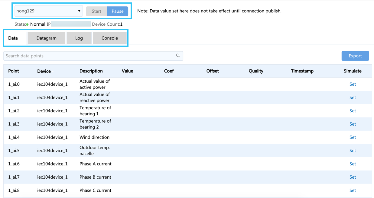
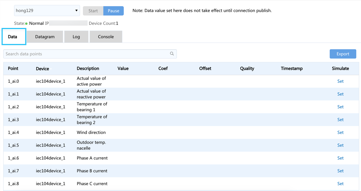
Batch testing provides four features: data, datagram, log, and console. Click the corresponding tab to switch among the different features, the operations of each page are described in the below sections:
Data
In the Data tab, you can view all the devices under this connection, filter the devices to see the update of the collection point data and set numbers for telemetry and telecommand points:
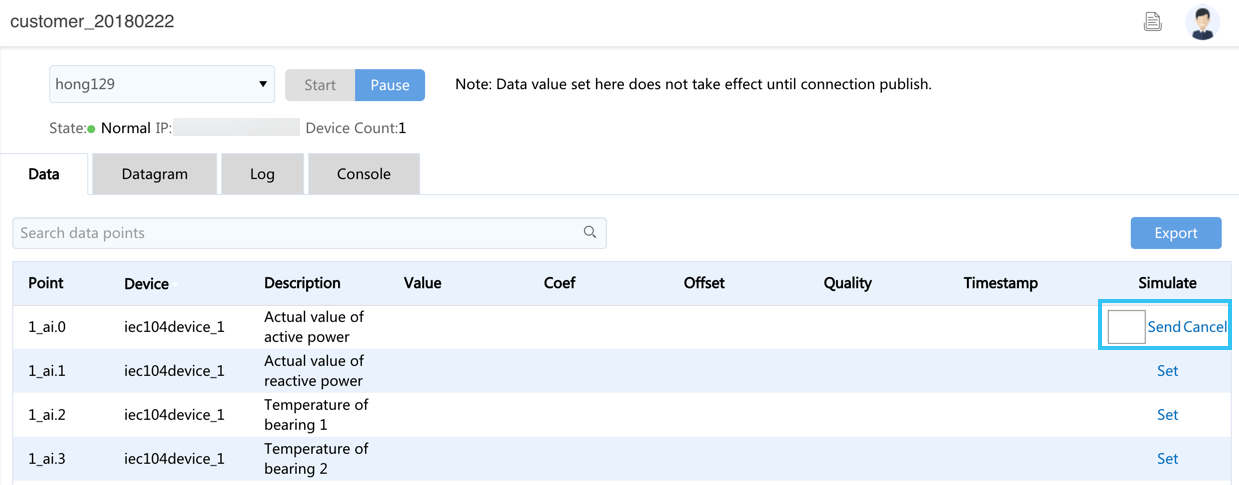
Setting number
You can set numbers for the telemetry and telecommand points in the following approach:
Click Set to set the value.
click Send to send the set value to the cloud. Click once to send one time, it will not interrupt the upload of the original data, equivalent to inserting a value to the cloud.
Datagram
In the Datagram tab, you can view and copy the incoming and outgoing datagram.
Log
In the Log tab, to avoid flooding of information, the system hides the logs of info types and only displays logs of warning and error types to assist the user in diagnosing the cause of the communication error.
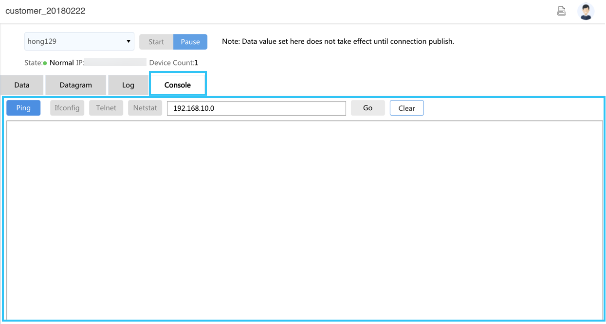
Console
In the Console tab, you can debug through the common communication debugging commands. The most frequently used debugging commands are including:
Test basic ping test (You’ll need to enter the IP address of the ping in the input box)
Check local IP
Telnet Test(You’ll need to enter the IP and port number.)
Check TCP connection
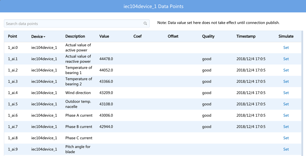
Testing the Communication of a Single Device
You can test the communication on a single device and view the corresponding data.
Click View after the device to be tested.
In the pop-up window, you can test the view the detailed information and set the telemetry and telecommand points which the operations are same as the bulk communication test.
Summary
After the connection configuration of the sub-devices is completed in the Edge gateway, the data of these sub-devices is automatically sent to the EnOS cloud.