Creating and Managing Device Templates
A device template works as a bridge for device connection, which consists of two parts:
The protocol.
The mapping relationship of the device measuring points.
For an actual device, the names of the measuring points are often customized, and cannot be identified directly by the system. Therefore, it is necessary to map the customized actual measure points to the domain points of the standard device models. On the other hand, protocol configuration is also required for device connection.
About This Task
The following major steps are involved:

A device template can be created mainly in two ways:
Created from scratch.
Created and modified based on an existing device template. You can choose this method when the scenario requires a device template that is similar to an existing one. By copying an existing template and slightly modifying to obtain a new template, in order to reduce your workload.
Creating a Device Template from Scratch
You can create a device template from scratch in the following approach:
In the EnOS cloud, click EnOS Edge > Templates from the left navigation menu.
Click New Template.
In the pop-up window, enter the basic device information and select a device model.
Click Save to create the template.
Click
 after the newly created template.
In the Detail page, follow the instructions below to configure a device template.
The device template includes the basic info editing, the point table upload, and the mapping relationship configuration.
Configuring Basic Info
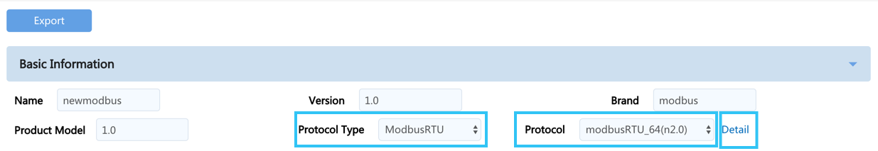
In the Basic Information section, provide the information of the device, among this settings:
You can view and select the general protocols supported by the EnOS Edge as well as their associated templates. To view the description of each protocol so as to choose the right template, you can click on the Detail next to the protocol field and move the cursor to the
 icon in the window that appears.
Note
If no suitable protocol is found, you can contact the system administrator. You can also re-develop the protocol and upload it to the protocol management center for editing, updating, and more operations. For information on developing new protocols, please refer to [Creating Protocol](creating_protocol).
Uploading Point Table
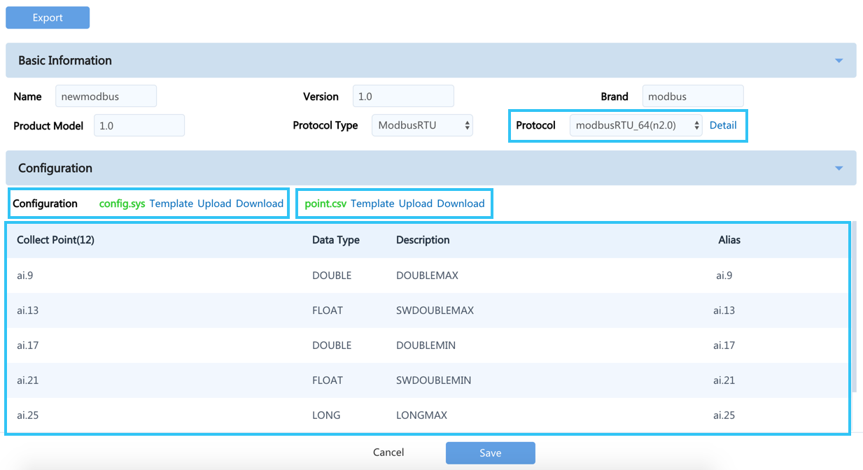
In the Configuration section, you need to edit two configuration files:
config.sysis a parameter configuration file relating to communication protocols.point.csvis the actual measuring point table of the device.
Download the
config.sysandpoint.csvtemplates.Edit both templates according to your business needs.
Note
The
point.csvpoint table must be in UTF-8 BOM format to avoid display errors and other issues.Click Upload to upload the both templates.
Note
If there are values in the
aliascolumn of thepoint.csvtable when you are updating the table (For example, uploading a new point table), you need to first upload an empty point table to overwrite the original table before uploading the actual point table to avoid errors.
If you have chosen a communication protocol in the previous step and successfully uploaded the point.csv table here, you will see the measuring point information in the point.csv table, as shown in the following figure:
Selecting Model and Configuring Mapping Relationship
In the Model Selection and Mapping section, you can configure mapping relationships to match customized actual points with the standard device model points. The main steps include:
Select a standard device model in the Device Model field.
Find the measuring point for which a mapping configuration is required, and click
 after the standard model point.
In the pop-up window, select the actual measuring point or enter a keyword in the search bar to search for the measuring point:
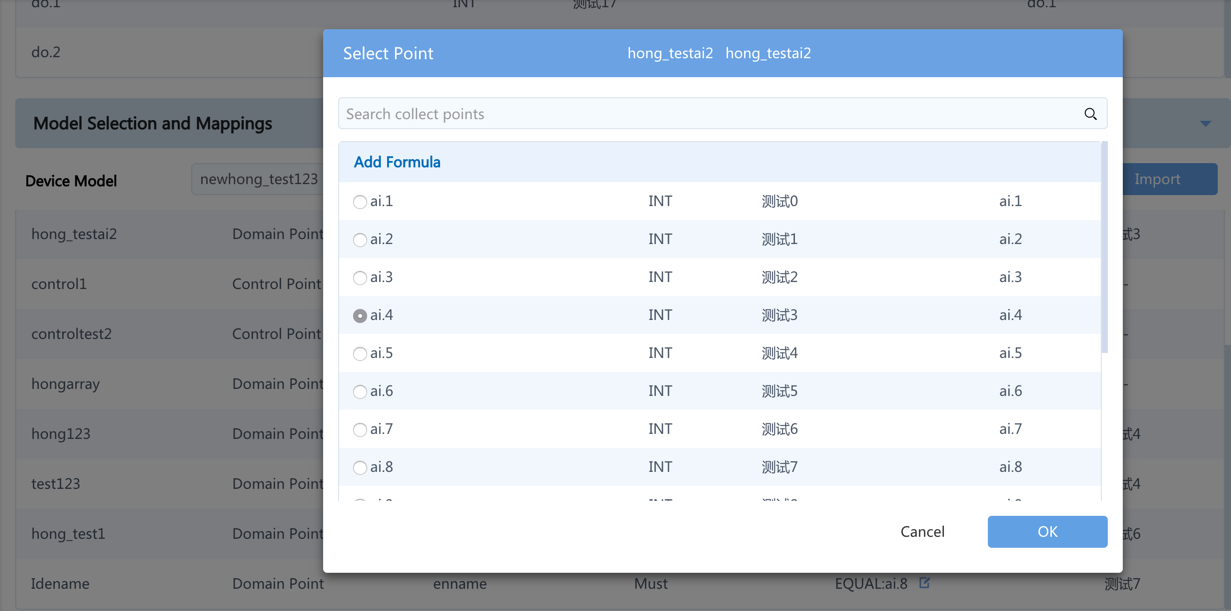
Add the mapping relationship:
If it is a simple one-to-one mapping, just check the corresponding measuring point.
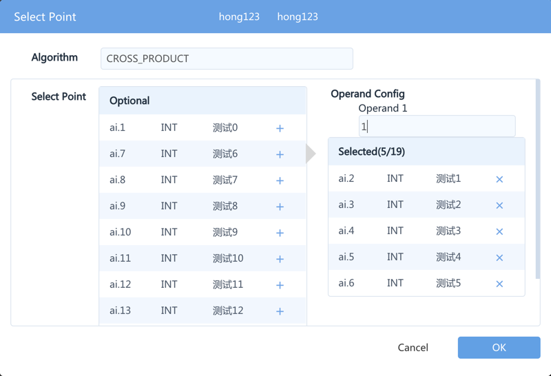
For complex mappings, you can click Add Formula to configure a mapping formula:
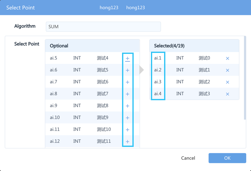
Take the addition formula “SUM” as an example:
select SUM in the formula algorithm column.
In the acquisition point box, click
 next to the corresponding point in the order of adding the points. As you can see in the figure below, the added formula is “ai.4999+ai.5001”, consistent with the order of clicking.
Note
For some formulas, the order of adding the points is important. For example, in the cross product operation, when you select cross product in the formula algorithm column and then select four points in order, the added formula will be “(ai.4999*ai.5000+ai.5009*ai.5010)”. The operand column in the figure works as a coefficient; if it is set to 0, no operation will be made. The operand in the figure below is 0.01, so the final formula added is “(ai.4999*ai.5000+ai.5009*ai.5010)*0.01”.
Batch Configuration of Mapping Relationship
In the Model Selection and Mapping section, you can configure all the mappings at once by performing the following steps:
Click Export to download the mapping table of the domain points.
In the table, You only need to enter the numbers of acquisition points in the mapping column of the mapping relationship table; the mdesp column is used to describe the acquisition points, which can be left empty.
Save the table.
Click Import to upload the mapping table.
After successfully uploading the mapping relationship table, download the list of domain points to obtain a table that contains mapping relationship. The table now includes the description of acquisition points (because the description can be automatically obtained from the configuration file
point.csv)After configuring the mapping relationship, you can see the number and description of the acquisition points of each corresponding standard model point.
Click Save to finish the device template editing.
Note
Depending on the application requirements of the domain, a device model point may or may not require mapping relationship configuration. Perform configuration based on your needs;
Points that require a formula for mapping must be added manually, and must not be operated directly via import/export;
In the exported mapping relation table, the points that are mapped through formulas do not appear in the exported CSV file, but the formula exists in the backstage.
Creating a Device Template by Cloning
You can view all the device templates of the current OU on the Templates page. When the device template required by a new device is similar to an existing device template, you can copy and modify the existing template in order to reduce the workload.
In the Template page, find the device template to be cloned and click Copy.
In the pop-up windows, enter a unique name for the new device template.
Click Save to complete the creation.
Click
after the newly created device template to edit the template according to your requirement.
Modifying and Deleting Device Templates
In the Template page:
To modify a template, click
after the template to be edit to enter the template details page of the target device.To delete a template, click
 after the template to be delete.
Note
When modifying or deleting a template that is in use, as the operation will affect all the device instances that are using the template.