Getting Started: Integrating Data from Third-Party System
This task helps you get started with EnOS Device Data Integration Service with a scenario that stemmed from real customer needs.
About This Task
A third-party system uploads device data via HTTP. When the device data is uploaded to EnOS, an integration flow receives the message with HTTP Server and then map the uploaded message to an asset defined in EnOS. Finally, the flow converts the message into the standard EnOS-defined JSON and integrates the message data.

This task has the following steps.
Create Model
Create Integration Flow
Design Flow
Publish and Start Flow
Prerequisites
Ensure that you have requested for the Data Integration Resource.
Step 1: Creating Model
This step assumes that there is no existing device model that can be used. Create a new model named city_iems_cctv with the features defined as per the below. For more information about models, see Creating a Model.
Feature Type |
Name |
Identifier |
Data Type |
Value |
|---|---|---|---|---|
Attributes |
Device ID No. |
device_id_no |
string |
city_iems_cctv |
Measurement Points |
Event Name |
alarm_data_event_name |
string |
1024 |
Measurement Points |
People Count |
raw_data_count |
string |
1024 |
Measurement Points |
People Count Percentage |
raw_data_count_percentage |
string |
1024 |
Measurement Points |
Image Path |
raw_data_imgpath |
string |
1024 |
Measurement Points |
Object Type |
raw_data_objtype |
string |
1024 |
Measurement Points |
Raw Image Path wo OBB |
raw_data_patch |
string |
1024 |
Measurement Points |
People Association |
raw_data_pplassoc |
string |
1024 |
Measurement Points |
Raw Image Path wo BB |
raw_data_rawimgpath |
string |
1024 |
Measurement Points |
Bounding Box |
raw_data_rect |
string |
1024 |
Measurement Points |
Event Start Time |
raw_data_start_time |
string |
1024 |
Measurement Points |
Time Stamp |
raw_data_timestamp |
string |
1024 |
Measurement Points |
Time Stamp Unix |
raw_data_timestamp_unix |
string |
1024 |
Measurement Points |
Track ID |
raw_data_track_id |
string |
1024 |
Measurement Points |
Video Path |
raw_data_videopath |
string |
1024 |
Measurement Points |
Camera ID |
raw_stream_camera |
string |
1024 |
Measurement Points |
Region of Interests |
raw_stream_roi |
string |
1024 |
Measurement Points |
Streaming ID |
raw_stream_streamingID |
string |
1024 |
Measurement Points |
Zone |
raw_stream_zone |
string |
1024 |
Step 2: Creating Integration Flow
Log in to the EnOS Management Console and click Device Data Integration > Flow Designer from the left navigation menu.
Click New Integration Flow > Create from Scratch, enter the flow name and description, and click OK.
Step 3: Designing Integration Flow
You will enter the Flow Designer page with a blank canvas. A list of nodes will be displayed on the left.
Design the flow with the following nodes in the order shown below.

Add the HTTP Server node to the Flow Designer canvas to create an HTTP server. Select Anonymous in Authorization. The URL will be automatically assigned by Device Data Integration Service and cannot be edited. For more information, see HTTP Server.
Add the Script node to the canvas and name it Auth. Go to the Script tab, delete the default code, and enter the following.
var timestamp = metadata.get("Timestamp");
print("header timestamp :" + timestamp);
var auth = metadata.get("Authorization");
print("header auth :" + auth);

var body = JSON.stringify(msg);
var appId = "maimnwk3";
var secretKey = "X56ZXY";

var rawData = appId + body + timestamp;
print("rawData :" + rawData);
var result = tools.HMACSHA256Util.encrypt(rawData, secretKey);

print("result :" + result);
if (result === auth) {
    return tools.resultBuilder.build(true, JSON.stringify(msg));
} else {
    return tools.resultBuilder.build(false);
}
return tools.resultBuilder.build(true, JSON.stringify(msg));
For more information about the Script node, see Script.
Add another Script node to the canvas and name it Parse Data. Go to the Script tab, delete the default code, and enter the following.
if (!msg.Data) {
    return tools.resultBuilder.build(false);
}
var dataArray = msg.Data.data;
var stream = msg.Data.stream;
var device_id = stream.camera;
var flag = true;

for (var i = 0; i < dataArray.length; i++) {
    var data = dataArray[i];
    if (!data.eventName) {
        flag = false;
        break;
    }

    var paramsArray = new Array();
    if (data.eventName === "Abandon") {
        var mps = {};
        mps["raw_data_count"] = JSON.stringify(data.count);
        mps["alarm_data_event_name"] = data.eventName;
        mps["raw_data_imgpath"] = JSON.stringify(data.imgpath);
        mps["raw_data_objtype"] = data.objType;
        mps["raw_data_pplassoc"] = data.peopleassociation;
        mps["raw_data_rawimgpath"] = JSON.stringify(data.rawimgpath);
        mps["raw_data_rect"] = JSON.stringify(data.rect);
        mps["raw_data_start_time"] = data.startTime;
        mps["raw_data_track_id"] = data.trackId;
        mps["raw_data_timestamp"] = data.timestamp;
        mps["raw_data_timestamp_unix"] = data.tsUnix;
        mps["raw_data_videopath"] = JSON.stringify(data.videopath);
        mps["raw_data_patch"] = JSON.stringify(data.patch);
        mps["raw_stream_camera"] = stream.camera;
        mps["raw_stream_roi"] = stream.roi;
        mps["raw_stream_streamingID"] = stream.streamingID;
        mps["raw_stream_zone"] = stream.zone;

        var timestamp = data.timestamp;
        var params = {};
        params["measurepoints"] = mps;
        params["time"] = new Date().getTime();
        params["device_id_no"] = device_id;
        paramsArray.push(params);
    } else if (data.eventName == "CrowdAlert") {
        var mps = {};
        mps["raw_data_count_number"] = data.count.number;
        mps["raw_data_count_percentage"] = data.count.percentage;
        mps["alarm_data_event_name"] = data.eventName;
        mps["raw_data_imgpath"] = JSON.stringify(data.imgpath);
        mps["raw_data_objtype"] = data.objType;
        mps["raw_data_pplassoc"] = data.peopleassociation;
        mps["raw_data_rawimgpath"] = JSON.stringify(data.rawimgpath);
        mps["raw_data_rect"] = JSON.stringify(data.rect);
        mps["raw_data_start_time"] = data.startTime;
        mps["raw_data_track_id"] = data.trackId;
        mps["raw_data_timestamp"] = data.timestamp;
        mps["raw_data_timestamp_unix"] = data.tsUnix;
        mps["raw_data_videopath"] = JSON.stringify(data.videopath);
        mps["raw_stream_camera"] = stream.camera;
        mps["raw_stream_roi"] = stream.roi;
        mps["raw_stream_streamingID"] = stream.streamingID;
        mps["raw_stream_zone"] = stream.zone;

        var timestamp = data.timestamp;
        var params = {};
        params["measurepoints"] = mps;
        params["time"] = new Date().getTime();
        params["device_id_no"] = device_id;
        paramsArray.push(params);
    } else {

    }
}

if (!flag) {
    return tools.resultBuilder.build(false);
}

return tools.resultBuilder.build(true, JSON.stringify(paramsArray));
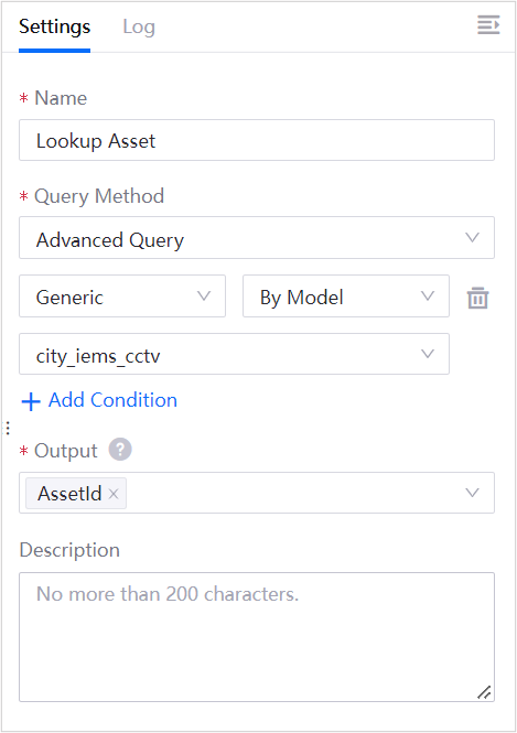
Add the Lookup Asset node to the canvas and configure the node as per the below. For more information about the Lookup Asset node, see Lookup Asset.

Add the Upload Measurement Point node to the canvas. For more information aboute the Upload Measurement Point node, see Upload Measurement Point.
Link all the nodes together as per the image above.
Toggle on the Debug switch on the top right to record the logs of the nodes in the flow.

Click Save
 .
.
Step 4: Publishing and Starting Integration Flow
Click Publish
 for the flow you have created.
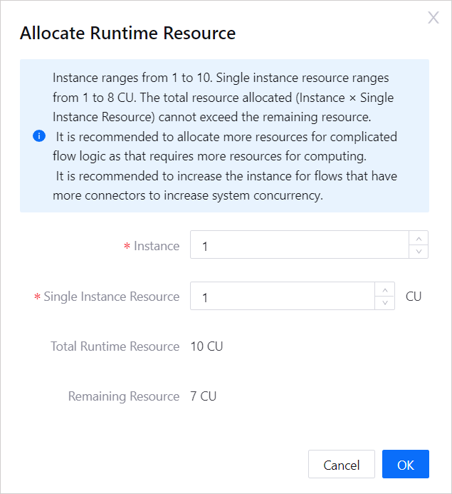
Allocate the runtime resources needed for the flow and click OK.

On your local machine, use POSTMAN to send a request to the HTTP server node, containing the following message as the payload.
{
    "Data":{
        "data":[
            {
                "eventName":"Abandon",
                "count":1,
                "imgpath":10,
                "objType":"test",
                "peopleassociation":"xxx",
                "rawimgpath":10,
                "rect":10,
                "startTime":"2020-09-15 10:00:00",
                "txUnix":"xx",
                "vediopath":"xxx",
                "patch":"xxx",
                "camera":"xxx",
                "rox":"xxx",
                "streamID":"",
                "zone":"xxx"
            }
        ],
        "stream":{
            "device_id":"xxxxxId"
        }
    }
}
Results
In Device Data Integration > Flow Designer, click Edit to enter the integration flow canvas page.
Click the Log
 above the flow canvas to see the flow running logs.
Click the Log tab of each node (if applicable) to see their respective inputs and outputs.